martedì 22 gennaio 2013

Basis of logic gates

This post is about logic gates, those one are the basis of calculation in base 2 (so also of computers).
In this post I'll talk about three logic gates:
-not
-and
-or

NOT Gate
The not gate return the opposite of the input. Here is the truth table:
in out
0   1
1   0

This is the standard symbol of NOT gate:


AND Gate
The and gate return positive just if all the inputs are positive. Here is the truth table:
a b out
0 0   0
0 1   0
1 0   0
1 1   1

This is the symbol of AND gate:


OR Gate
The or gate return positive just if one input is positive. Here is the truth table:
a b out
0 0   0
0 1   1
1 0   1
1 1   1

This is the symbol of OR gate:


This gates can be created using transistors like BC547, here is a short summary about logic gates made using transistors:


You can also download a pdf of this summary here.

Here are some photos of logic gates made using transistors:


I hope you like this post, if you have any question comment or send me an email to damianoandre@gmail.com

Bye, Dami

venerdì 4 gennaio 2013

Some Google easter eggs

Hi, this post is about some funny easter eggs of Google:
-type "askew" to make the page tilt
-type "do a barrel roll" to make the page rotate of 360°
-type "zerg rush" to start a little arcade game
-type "where is chuck norris" and click I'm feeling lucky
-type "google gravity" and click I'm feeling lucky to see Google home page affected by gravity
-go to Google reader and press in order this keys to make some little ninja appear on the left:
Up, Up, Down, Down, Left, Right, Left, Right, B, A

Here is a sample video:


I hope you like this post, if you have any question please comment or send me an e-mail to damianoandre@gmail.com

Bye, Dami

domenica 23 dicembre 2012

Two years of blogging: special post about paper nativity scene + bare paint + arduino

Hi, yesterday  was my second blogging anniversary and I'm writing a special post: a nativity scene made of paper and lighted up using LEDs, bare paint and arduino.
Here are some file that I found useful to make it.
I won't explain anything about this project because I think that using tools like Arduino and Bare Paint the only limit you have is your imagination, so I just suggest to make the scene being alive using LEDs, servo motors and whatever you want.
Here are some photos of the project:


LEDs connected to power using Bare Paint

LEDs connected to power using Bare Paint
 

The paper house

Arduino connected with Bare Paint to LEDs


The result


 And here is a video:

I hope you like the post, Merry Christmas and thanks for your support during these two years.
If you have any question comment or send me an e-mail to damianoandre@gmail.com

Bye, Dami

martedì 11 dicembre 2012

Conductive Paint, write circuits on paper

Hi today I'm posting about Bare Conductive Paint (http://bareconductive.com/), a conductive ink that you can use on paper and textiles to write circuits.
Here are the  Bare Pens (5 pens --> about 25£):


Here are some photo of a simple project to test this paint:


I think this paint it's great for everyone who like electronics, I will post soon about a project made using Bare Paint.
If you have any question comment, send me an email to damainoandre@gmail.com or check http://bareconductive.com/

Bye, Dami


sabato 1 dicembre 2012

2 thousands views in November!

I write this post to say that November was highscore month: more than two thousands views.
Since I've started posting this blog reached about 28000 views, for me it's a great goal and I'll try to get always more views, this doesn't mean I'll post everyday because for me blogging it's just an hobby.

Bye, Dami

venerdì 30 novembre 2012

Volumetric lighting in Blender

Hi, this psot is about how to create a volumetric light in blender.
Here is an example of volumetric light:


There is only a lamp type that support volumetric lighting in blender: the spot.
First of all add the spot(Optional: in the lamp properties check Show cone to see how light influence your scene). Then go in lamp properties and in Spot Shape submenu check Halo and edit Step to 12.
Now you have created a volumetric light but if you wanna get a better result (not always, but sometimes  using this it looks more realistic) activate Ambient Occlusion and Indirect Lighting int the World Properties.
I hope you found this post useful, if you have any question comment or send me an e-mail to damianoandre@gmail.com

Bye, Dami

lunedì 12 novembre 2012

Use Arduino to program AVR

Hi, today I'm posting about programming an AVR (such as an attiny85) using Arduino.
You'll need:
- one LED
-10 microfarad capacitor
-an AVR (in my case an attiny85)
-an Arduino board (in my case Arduino UNO)
-some wires

First of all open the Arduino IDE and upload the ArduinoISP sketch (you can find it in File>Examples)
If you are using arduino 1.0 software check that in the void heartbeat() there is a line that says delay(20) if not change it.
When you have uploaded it to Arduino disconnect the board from pc and connect your avr like this:
-Arudino GND to AVR GND
-Arduino 5v to AVR VCC
-Arduino pin 10 to RST pin on AVR
-Arduino pin 11 to MOSI pin on AVR
-Arduino pin 12 to MISO pin on AVR
-Arduino pin 13 to SCK pin on AVR
-10 microfarad capacitor  between GND and Reset on Arduino

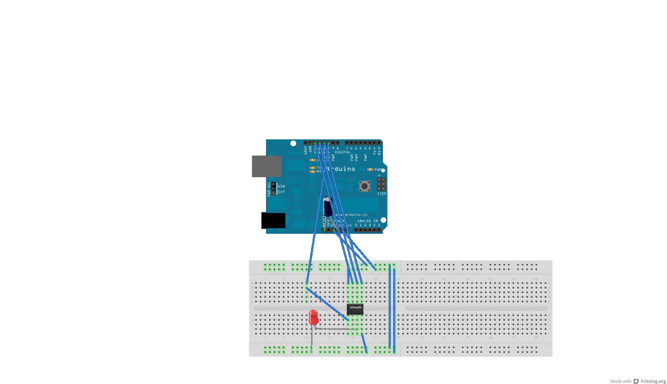
If you are using an Attiny85/45/13 it should look like this:


Now hardware side everything it's done.
To compile and upload the code for the AVR we need a software like WinAVR.
Download and install it, then create a C source file with your code in my case this:
 
#include <avr/io.h>
#define F_CPU 1000000UL
#include <util/delay.h>

int main(void) {
    int n;
    DDRB |= ( 1 << 4 );
    while (1) {
        PORTB &= ~(1 << 4 );
        _delay_ms(1000);
        PORTB |= ( 1 << 4 );
        _delay_ms(1000);
    }
    return 0;
}

Now you're ready to compile and upload your code:
-connect arduino to USB
-navigate to code folder using cd command
-compile your code using these commands:
for attiny13:
avr-gcc -g -Os -c -mmcu=attiny13 test.c
avr-gcc -mmcu=attiny13 test.o -o test.elf
avr-objcopy -O ihex -R .eeprom test.elf test.hex
 
for attiny85/45:
avr-gcc -g -Os -c -mmcu=attiny85 test.c
avr-gcc -mmcu=attiny85 test.o -o test.elf
avr-objcopy -O ihex -R .eeprom test.elf test.hex 

check this for more commands.

-upload your code with this command:

avrdude -P COM4 -p t13 -c avrisp -b 19200 -U test.hex
 
If you're using a different port change COM4.
 
Now everything it's done and the AVR should be programmed.


Here are some photos of the project:


I hope you like this post, if you have any question comment or send me an e-mail to
damianoandre@gmail.com 

Bye, Dami

lunedì 29 ottobre 2012

Horror corridor made using blender

Hi today I'm posting about creating an horror corridor using blender, I think that it's simple to make it but the result it's cool, here is the final render:


And here is the download of the blender project(.blend).

I hope you like this post, if you have any question please comment or send me an e-mail to damianoandre@gmail.com

Bye, Dami