Visualizzazione post con etichetta arduino. Mostra tutti i post

giovedì 26 giugno 2014

Arduino color detector

Hi guys I'm here with a really nice project: recognise colors with arduino.
It uses a particular property of colors:
The color of an object depends on both the physics of the object in its environment and the characteristics of the perceiving eye and brain. Physically, objects can be said to have the color of the light leaving their surfaces, which normally depends on the spectrum of the incident illumination and the reflectance properties of the surface, as well as potentially on the angles of illumination and viewing. (from wikipedia)
First of all we are talking about objects which don't emit light by themselves.
Then we know that the color we sense is the light that an object reflects, so:
if we know exactly the quantity of light that goes to an object and then with a sensor we measure the quantity that has been reflected we can know the color of the object.
 
The main "problems" are two: we have to do this 3 times (for red, green, blue light), the result is influenced by sources of light we can't control (environmental lights).
The solution to the first problem is simply the repetition of the code three time; for the second problem we have to make a calibration for the sensor.
This calibration consist of gathering the maximum and the minimum light that an object can reflect in this particular environment (we have to do also this 3 times).

Hardware:
you'll nedd:
-an arduino
-an RGB led
-a photoresistor
-2x 10Kohm resistor
-a 220ohm resistor
-a pushbutton
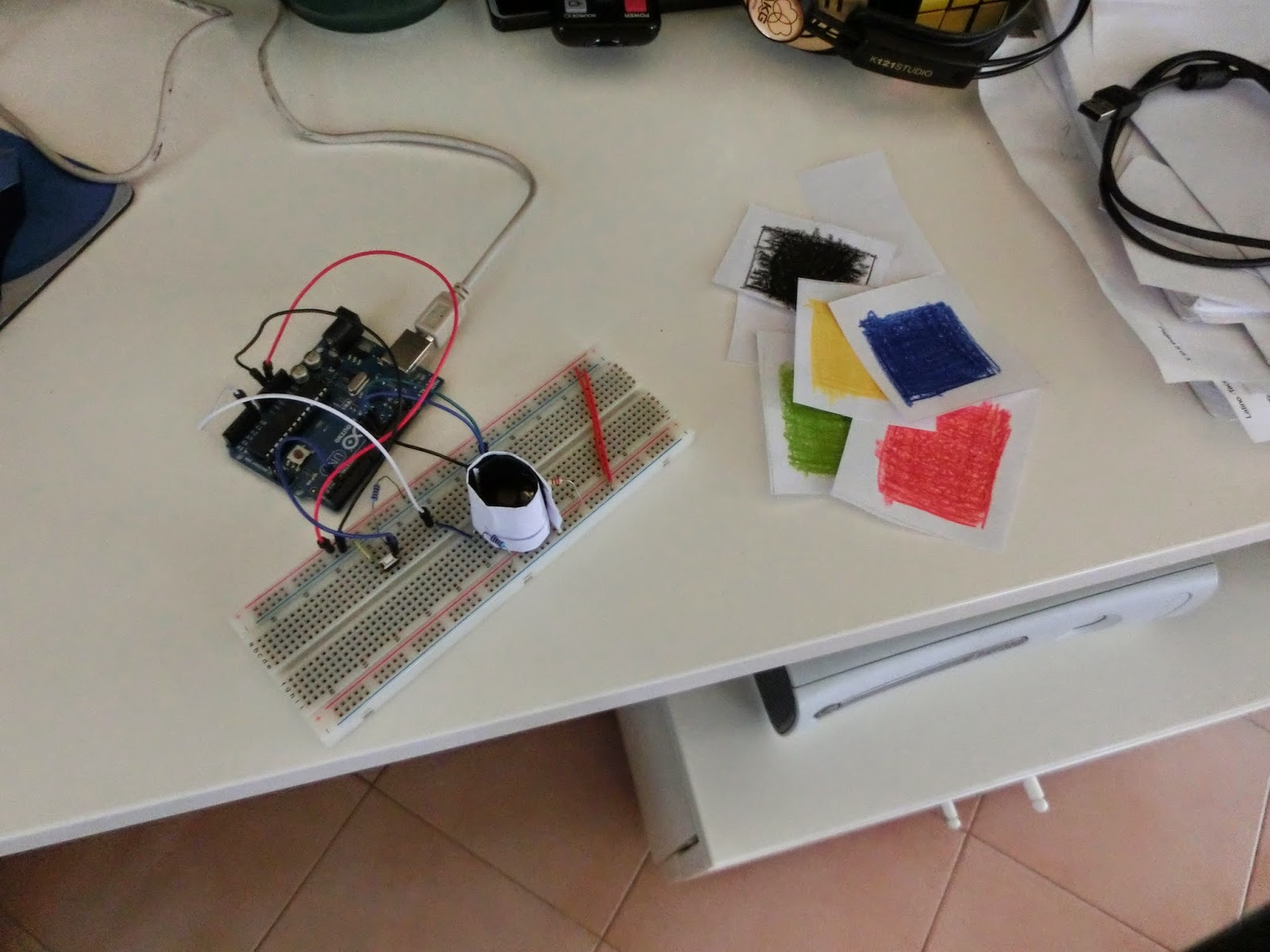
then assemble everything this way:


Here is the arduino code:

/*
Color detector with arduino, RGB led and photoresistor
Code by Damiano Andreghetti (also thanks to the adafruit tutorial about the RGB led)
for more information check my blog: www.ilblogdidami.blogspot.com

Everyone is free to use this code, but I would appreciate if you mention my name
*/

int redPin = 11;
int greenPin = 9;
int bluePin = 10;
int buttonPin = 2;
int buttonState = 0;
int phrPin = 0; //photoresistor pin

//other variables for calibrating and measuring
float calwr, calwg, calwb, calbr, calbg, calbb, r, g, b = 0;


//uncomment this line if using a Common Anode LED
#define COMMON_ANODE

void setup(){
  pinMode(redPin, OUTPUT);
  pinMode(greenPin, OUTPUT);
  pinMode(bluePin, OUTPUT);
  pinMode(buttonPin, INPUT);
  pinMode(phrPin, INPUT);
  Serial.begin(9600);
}
    
void loop(){
  buttonState = digitalRead(buttonPin);
  if(buttonState == 0){
    Serial.println("button pressed: calibrating white");  
    calibration();
  }
  else{
    measure();
  }
}

float readColor(int times){
  float avg, total, current = 0;
  for(int n = 0; n <= times; n++){
    current = analogRead(phrPin);
    total += current;
    delay(20);
  }
  avg = total/times;
  return avg;
}

void setColor(int red, int green, int blue){
  #ifdef COMMON_ANODE
  red = 255 - red;
  green = 255 - green;
  blue = 255 - blue;
  #endif
  analogWrite(redPin, red);
  analogWrite(greenPin, green);
  analogWrite(bluePin, blue);
}

/*
This function is needed because the raw measure is influenced by
environmental light.
*/
void calibration(){
  //first calibrate with white color
  setColor(255, 0, 0);
  delay(100);
  calwr = readColor(7);
  setColor(0, 255, 0);
  delay(100);
  calwg = readColor(7);
  setColor(0, 0, 255);
  delay(100);
  calwb = readColor(7);
  setColor(0, 0, 0);
  //then wait until the button is pressed again
  //so we can calibrate with black color
  Serial.println("waiting to calibrate black");
  for(int i = 0; i <= 10; i+=0){
    buttonState = digitalRead(buttonPin);
    if(buttonState == 0){  
      //calibrate with black color
      setColor(255, 0, 0);
      delay(100);
      calbr = readColor(7);
      setColor(0, 255, 0);
      delay(100);
      calbg = readColor(7);
      setColor(0, 0, 255);
      delay(100);
      calbb = readColor(7);
      setColor(0, 0, 0);
      i = 20;
    }
    else{
      //nothing
    } 
  }
}
 
void measure(){
  float deltacal = 0;
  setColor(255, 0, 0);
  delay(100);
  deltacal = calwr-calbr;
  r = (readColor(7) - calbr)/(deltacal)*255;
  setColor(0, 255, 0);
  delay(100);
  deltacal= calwg-calbg;
  g = (readColor(7) - calbg)/(deltacal)*255;
  setColor(0, 0, 255);
  delay(100);
  deltacal = calwb-calbb;
  b = (readColor(7) - calbb)/(deltacal)*255;
  Serial.print(int(r));
  Serial.print(",");
  Serial.print(int(g));
  Serial.print(",");
  Serial.println(int(b));
}


Now upload this code to the arduino.
To calibrate the sensor press one time the button (the sketch check the button status before the red light) while a white object is near the sensor, then the led turns off.
Now put a black object near the sensor and push the button another time.

The arduino will start writing via serial the RGB value it detects.


Now we're going to use processing to display the result.
Here is a simple sketch:

/*
Sketch used to display the result of the color detector made with arduino
Code by Damiano Andreghetti based on processing serial
for more information and for the arduino schematic and code
check my blog: www.ilblogdidami.blogspot.com

Everyone is free to use this code, but I would appreciate if you mention my name
*/

import processing.serial.*;

Serial port;  // Create object from Serial class
String buff;  // Data received from the serial port
int r,g,b = 0;

void setup() {
  size(600, 600);
  noStroke();
  // List all the available serial ports in the output pane.
  // You will need to choose the port that the Wiring board is
  // connected to from this list. The first port in the list is
  // port #0 and the third port in the list is port #2.
  println(Serial.list());


  // use your port
  port = new Serial(this, Serial.list()[1], 9600);
}

void draw() {
  if (0 < port.available()) { 
    buff = port.readString();
    String[] list = split(buff, ',');
    if(list.length == 3){
      r = int(list[0]);
      g = int(list[1]);
      b = int(list[2]);
      background(r,g,b); 
      }
    else{
      background(r,g,b);
      }
    }
  else{
    background(r,g,b);
    }


To make everything work connect the arduino, calibrate the sensor, and run the processing sketch.
If there are some problems re-calibrate the sensor and use a dark-color cylinder to isolate LED and resistor from the environment. Like this:


Here are other photos of the project:


Here is also a video of the project:


I hope you like this post, if you have any question comment or send me an email to damianoandre@gmail.com

Bye, Dami

martedì 10 giugno 2014

Timelapse tutorial (with arduino and digital reflex camera)

Hi guys, today I'll talk about making a timelapse video.
For those who don't know what's a timelapse video, here  is mine:


First of all the components:
-digital camera (nikon, canon, olympus, pentax, sony)
-arduino (any board, UNO, MEGA, duemilanove ecc..)
-IR transmitter led
-220 ohm resistor

For making a timelapse video our camera has to take a photo from the same position each 15/20 sec (depending on what you're trying to do) and probably you don't want to take each picture by yourself, so you'll need an arduino.
First of all connect the led and the resistor to the arduino in this way:


Then using this really nice library our Arduino will shut photos.
Install the library and open arduino IDE.
Then go to File>Examples>MultiCameraIrControl and select your camera brand.
Now just change the loop function like this:

void loop(){
  D600.shutterNow();
  delay(10000);
}


delay function will wait the give milliseconds before shutting another photo; I think 10 seconds are good for many videos but depending on your subject you would have to change this value.

Another part of this project is powering arduino and camera for many hours.
For the camera use the normal power supply and for the arduino I suggest using a 110V/220V--->USB transformer (probably you have one at home, they are used for smartphones or other devices).

The last part of the project is calculating how long we can shoot depending on delay between photos and camera's memory.

For example if I have a 32GB SD and I take a photo every 10 seconds (5MB each photos) I'll be able to shoot photos for: (32'000MB / 5MB ) * 10 sec

Make your own calculation but remember: this works only in theory: there are other variables (battery duration ecc..)

Now you just need to turn on your camera, turn on the remote control mode (look in the instructions), power the arduino and place it in front of your camera as a remote control.

Here is my short timelapse:


I hope you enjoyed this project, if you have any question comment or send me an email to damianoande@gmail.com

Bye, Dami

domenica 22 settembre 2013

Arduino ultrasonic distance measurement

Hi guys' today I'm here with a tutorial about interfacing arduino with ultrasonic distance meter like the HC-SR04.
First of all, the theory:

If we know that the sound take a time to reach the obstacle and come back and that
speed s is equal to s=d/t where d is the distance then d=s*t .
We consider that speed of sound is 340.29 meters/seconds that is equal to
0.034029 centimeters/microseconds.

Now let's see the hardware parts, which is very simple:


To start measuring distance you just have to upload this code to the arduino
int trigPin = 2;
int echoPin = 4;

void setup() {
  Serial.begin(9600);
}

void loop(){
  long duration;
  float cm;
  pinMode(echoPin, INPUT);
  pinMode(trigPin, OUTPUT);
  digitalWrite(trigPin, LOW);
  delayMicroseconds(2);
  digitalWrite(trigPin, HIGH);
  delayMicroseconds(10);
  digitalWrite(trigPin, LOW);
  duration = pulseIn(echoPin, HIGH);
  cm = microsecondsToCentimeters(duration);
  Serial.print(cm);
  Serial.print("cm");
  Serial.println();
  delay(100);
}
float microsecondsToCentimeters(long microseconds){
  return (microseconds*0.034029)/2;
}


Here is a video of me testing this project:


I hope you like this post, if you have any question please comment or send me an email to damianoandre@gmail.com

Bye,Dami

mercoledì 4 settembre 2013

Use Arduino with RF Modules

Hi guys, today I'm here with a really cool project.
If you have ever wondered how to make 2 arduinos communicates without using expensive shield, here is the solution: there are some RF modules sold for about 2$ (transmitter + receiver)  that offer one way, easy-to-use communication with a range of about 150 meters.
In this post I'll explain how to use this modules.

First of all you'll need:
-2 arduinos
-a rf transmitter
-a rf receiver

STEP 1: the transmitter
Connect the transmitter to arduino this way:


Upload this code to the arduino connected to the transmitter:
 
#include <VirtualWire.h>
void setup(){
  vw_setup(2000); // bps
  }
void loop(){
  send("hello world"); //your message
  delay(1000);
  }
void send (char *message){
  vw_send((uint8_t *)message, strlen(message));
  vw_wait_tx();
  }

STEP 2: the receiver
Connect the receiver to the arduino this way:


Upload this code to the arduino connected to the receiver:

#include <VirtualWire.h>
byte message[VW_MAX_MESSAGE_LEN];
byte messageLength = VW_MAX_MESSAGE_LEN;
void setup(){
  Serial.begin(9600);
  Serial.println("Device is ready");
  vw_setup(2000); //bps
  vw_rx_start();
  }
void loop(){
  if (vw_get_message(message, &messageLength)){
    Serial.print("Received: ");
      for (int i = 0; i < messageLength; i++){
        Serial.write(message[i]);
        }
      Serial.println();
    }
  }

STEP 3: test ;)
Connect the 2 arudino and check with the serial monitor if it works


I hope you like this post, if you have any question please comment or send me an email to damianoandre@gmail.com

Bye, Dami

martedì 3 settembre 2013

Where to buy electronic parts for cheap

Hi guys Today I'm here with a tip about where to buy electronic parts(Arduino boards, LED, ICs, Arduino Shields, RF modules ecc...) for cheap.
 It's an ebay store located in Hong Kong, here is the link to the ebay page, I think it's a good seller beacuse it offers:
-really low prices
-good quality items
-more than 3000 items
-free shipping
The just thing I found not perfect is the slow shipping, but it's free so however it's good.
I hope you like this post,

Bye, Dami

martedì 2 aprile 2013

USB breadboard power supply

Today I'm posting about a simple USB breadboard 5v power supply I think there is nothing to explain, just take your solder and make an useful power supply for all your projects.
Here are some photos of mine:


I know this isn't a great post, but of course this is a nice tool that you can use for all your projects.
If you have any question comment or send me an e-mail to damianoandre@gmail.com

Bye, Dami

domenica 23 dicembre 2012

Two years of blogging: special post about paper nativity scene + bare paint + arduino

Hi, yesterday  was my second blogging anniversary and I'm writing a special post: a nativity scene made of paper and lighted up using LEDs, bare paint and arduino.
Here are some file that I found useful to make it.
I won't explain anything about this project because I think that using tools like Arduino and Bare Paint the only limit you have is your imagination, so I just suggest to make the scene being alive using LEDs, servo motors and whatever you want.
Here are some photos of the project:


LEDs connected to power using Bare Paint

LEDs connected to power using Bare Paint
 

The paper house

Arduino connected with Bare Paint to LEDs


The result


 And here is a video:

I hope you like the post, Merry Christmas and thanks for your support during these two years.
If you have any question comment or send me an e-mail to damianoandre@gmail.com

Bye, Dami

venerdì 10 febbraio 2012

Easy Arduino POV

This is a simple project about making a simple POV project using arduino.

What is POV?
 POV stands for Persistence Of Vision and here is a simple definition from wikipedia:
Persistence of vision is the phenomenon of the eye by which an afterimage is thought to persist for approximately one twenty-fifth of a second on the retina.
The POV can be used to write letters simply blinking LEDs.

About the project --> hardware
In the hardware side we only need to connect 7 LEDs to the pins from 2 to 8.

About the project  ---> software
First of all we need an array that contains the matrix of the font that we will write using POV.
This is a simple matrix that we're going to use for the project:

const byte font[][5] = {                     
        {0x00,0x00,0x00,0x00,0x00},   //   0x20 32 0
        {0x00,0x00,0x6f,0x00,0x00},   // ! 0x21 33 1
        {0x00,0x07,0x00,0x07,0x00},   // " 0x22 34 2
        {0x14,0x7f,0x14,0x7f,0x14},   // # 0x23 35 3
        {0x00,0x07,0x04,0x1e,0x00},   // $ 0x24 36 4
        {0x23,0x13,0x08,0x64,0x62},   // % 0x25 37 5
        {0x36,0x49,0x56,0x20,0x50},   // & 0x26 38 6
        {0x00,0x00,0x07,0x00,0x00},   // ' 0x27 39 7
        {0x00,0x1c,0x22,0x41,0x00},   // ( 0x28 40 8
        {0x00,0x41,0x22,0x1c,0x00},   // ) 0x29 41 9
        {0x14,0x08,0x3e,0x08,0x14},   // * 0x2a 42 10
        {0x08,0x08,0x3e,0x08,0x08},   // + 0x2b 43 11
        {0x00,0x50,0x30,0x00,0x00},   // , 0x2c 44 12
        {0x08,0x08,0x08,0x08,0x08},   // - 0x2d 45 13
        {0x00,0x60,0x60,0x00,0x00},   // . 0x2e 46 14
        {0x20,0x10,0x08,0x04,0x02},   // / 0x2f 47 15
        {0x3e,0x51,0x49,0x45,0x3e},   // 0 0x30 48 16
        {0x00,0x42,0x7f,0x40,0x00},   // 1 0x31 49 17
        {0x42,0x61,0x51,0x49,0x46},   // 2 0x32 50 18
        {0x21,0x41,0x45,0x4b,0x31},   // 3 0x33 51 19
        {0x18,0x14,0x12,0x7f,0x10},   // 4 0x34 52 20
        {0x27,0x45,0x45,0x45,0x39},   // 5 0x35 53 21
        {0x3c,0x4a,0x49,0x49,0x30},   // 6 0x36 54 22
        {0x01,0x71,0x09,0x05,0x03},   // 7 0x37 55 23 
        {0x36,0x49,0x49,0x49,0x36},   // 8 0x38 56 24
        {0x06,0x49,0x49,0x29,0x1e},   // 9 0x39 57 25
        {0x00,0x36,0x36,0x00,0x00},   // : 0x3a 58 26
        {0x00,0x56,0x36,0x00,0x00},   // ; 0x3b 59 27
        {0x08,0x14,0x22,0x41,0x00},   // < 0x3c 60 28
        {0x14,0x14,0x14,0x14,0x14},   // = 0x3d 61 29
        {0x00,0x41,0x22,0x14,0x08},   // > 0x3e 62 30
        {0x02,0x01,0x51,0x09,0x06},   // ? 0x3f 63 31
        {0x3e,0x41,0x5d,0x49,0x4e},   // @ 0x40 64 32
        {0x7e,0x09,0x09,0x09,0x7e},   // A 0x41 65 33
        {0x7f,0x49,0x49,0x49,0x36},   // B 0x42 66 34
        {0x3e,0x41,0x41,0x41,0x22},   // C 0x43 67 35
        {0x7f,0x41,0x41,0x41,0x3e},   // D 0x44 68 36
        {0x7f,0x49,0x49,0x49,0x41},   // E 0x45 69 37
        {0x7f,0x09,0x09,0x09,0x01},   // F 0x46 70 38
        {0x3e,0x41,0x49,0x49,0x7a},   // G 0x47 71 39
        {0x7f,0x08,0x08,0x08,0x7f},   // H 0x48 72 40
        {0x00,0x41,0x7f,0x41,0x00},   // I 0x49 73 41
        {0x20,0x40,0x41,0x3f,0x01},   // J 0x4a 74 42
        {0x7f,0x08,0x14,0x22,0x41},   // K 0x4b 75 43
        {0x7f,0x40,0x40,0x40,0x40},   // L 0x4c 76 44
        {0x7f,0x02,0x0c,0x02,0x7f},   // M 0x4d 77 45
        {0x7f,0x04,0x08,0x10,0x7f},   // N 0x4e 78 46
        {0x3e,0x41,0x41,0x41,0x3e},   // O 0x4f 79 47
        {0x7f,0x09,0x09,0x09,0x06},   // P 0x50 80 48
        {0x3e,0x41,0x51,0x21,0x5e},   // Q 0x51 81 49
        {0x7f,0x09,0x19,0x29,0x46},   // R 0x52 82 50
        {0x46,0x49,0x49,0x49,0x31},   // S 0x53 83 51
        {0x01,0x01,0x7f,0x01,0x01},   // T 0x54 84 52
        {0x3f,0x40,0x40,0x40,0x3f},   // U 0x55 85 53
        {0x0f,0x30,0x40,0x30,0x0f},   // V 0x56 86 54
        {0x3f,0x40,0x30,0x40,0x3f},   // W 0x57 87 55
        {0x63,0x14,0x08,0x14,0x63},   // X 0x58 88 56
        {0x07,0x08,0x70,0x08,0x07},   // Y 0x59 89 57
        {0x61,0x51,0x49,0x45,0x43},   // Z 0x5a 90 58
        {0x3c,0x4a,0x49,0x29,0x1e},   // [ 0x5b 91 59
        {0x02,0x04,0x08,0x10,0x20},   // \ 0x5c 92 60
        {0x00,0x41,0x7f,0x00,0x00},   // ] 0x5d 93 61
        {0x04,0x02,0x01,0x02,0x04},   // ^ 0x5e 94 62
        {0x40,0x40,0x40,0x40,0x40},   // _ 0x5f 95 63
        {0x00,0x00,0x03,0x04,0x00},   // ` 0x60 96 64
        {0x20,0x54,0x54,0x54,0x78},   // a 0x61 97 65
        {0x7f,0x48,0x44,0x44,0x38},   // b 0x62 98 66
        {0x38,0x44,0x44,0x44,0x20},   // c 0x63 99 67
        {0x38,0x44,0x44,0x48,0x7f},   // d 0x64 100 68
        {0x38,0x54,0x54,0x54,0x18},   // e 0x65 101 69
        {0x08,0x7e,0x09,0x01,0x02},   // f 0x66 102 70
        {0x0c,0x52,0x52,0x52,0x3e},   // g 0x67 103 71
        {0x7f,0x08,0x04,0x04,0x78},   // h 0x68 104 72
        {0x00,0x44,0x7d,0x40,0x00},   // i 0x69 105 73
        {0x20,0x40,0x44,0x3d,0x00},   // j 0x6a 106 74
        {0x00,0x7f,0x10,0x28,0x44},   // k 0x6b 107 75
        {0x00,0x41,0x7f,0x40,0x00},   // l 0x6c 108 76
        {0x7c,0x04,0x18,0x04,0x78},   // m 0x6d 109 77
        {0x7c,0x08,0x04,0x04,0x78},   // n 0x6e 110 78
        {0x38,0x44,0x44,0x44,0x38},   // o 0x6f 111 79
        {0x7c,0x14,0x14,0x14,0x08},   // p 0x70 112 80
        {0x08,0x14,0x14,0x18,0x7c},   // q 0x71 113 81
        {0x7c,0x08,0x04,0x04,0x08},   // r 0x72 114 82
        {0x48,0x54,0x54,0x54,0x20},   // s 0x73 115 83
        {0x04,0x3f,0x44,0x40,0x20},   // t 0x74 116 84
        {0x3c,0x40,0x40,0x20,0x7c},   // u 0x75 117 85
        {0x1c,0x20,0x40,0x20,0x1c},   // v 0x76 118 86
        {0x3c,0x40,0x30,0x40,0x3c},   // w 0x77 119 87
        {0x44,0x28,0x10,0x28,0x44},   // x 0x78 120 88
        {0x0c,0x50,0x50,0x50,0x3c},   // y 0x79 121 89
        {0x44,0x64,0x54,0x4c,0x44},   // z 0x7a 122 90
        {0x00,0x08,0x36,0x41,0x41},   // { 0x7b 123 91
        {0x00,0x00,0x7f,0x00,0x00},   // | 0x7c 124 92
        {0x41,0x41,0x36,0x08,0x00},   // } 0x7d 125 93
        {0x04,0x02,0x04,0x08,0x04},   // ~ 0x7e 126 94
    };


Then we need to set the pin in the setup() function:


void setup(){
  for(int i = 2; i <= 8; i++){ //I set the digital pin from 2 to 8 as OUTPUT pins
    pinMode(i, OUTPUT);
    }
  for(int i = 2; i <= 8; i++){ //I turn off the pins
    digitalWrite(i, LOW);
    }
  }


Now we have to use 2 for(;;) cycles, one for write each column (in this case 5, it depends from the matrix) and the other one for each row (or each LED). Now we use the bitRead() function to read the bit of a row and to turn on the LED if the bit value is 1.

void loop(){
  for(int col = 0; col < 5; col++){ //for each column
    for(int row = 0; row <=6; row++){ //and for each row  in a column:
      int val = bitRead(font[33][col], row); //I read the bit of the "A" byte at the current column and in the current row
      if(val==1){
        digitalWrite(row+2,  HIGH); // if the bit value is 1 I turn on the LED that represents the row
        }
      else{
        digitalWrite(row+2, LOW); // if the bit value is  0 I turn off the LED
        }
      }
      delay(3); //before starting  with the next column I delay 5 milliseconds
    }
    delay(100);
  }


You can download the full code at this link.

Here are some photos of the project:


I hope you enjoy this project, for more info comment or send me an e-mail to damianoandre@gmail.com

Bye, Dami

venerdì 28 ottobre 2011

Arduino and processing led blinking following music rythm

Hi,
Today I'm writing about a simple project with Arduino and Porcessing to blink 5 LEDs following the music rythm.
To do it we need an audio librari for processing called minim, (created by Damien di Fede) and we need the Firmata library for communicating to Arduino.
For this project you need:
-Arduino board
-5 LEDs (1,8-2v)
-5 220ohm resistors
-breadboard
-some wires
-arduino library for processing (http://www.arduino.cc/playground/Interfacing/Processing)
-minim audio library(http://code.compartmental.net/minim/distro/minim-2.0.2-lib.zip)

First of all prepare the simple connections on your breadboard following this image:


Then open the arduino software and upload the standardFirmata sketch (File>examples>Firmata>StandardFirmata).
Now, before writing the processing code I'd like to tell you something aboute the libraries we're going to use: Firmata is a library made for communciating between processing and Arduino. When you run Firmata in arduino, you can call arduino functions from processing using the arduino library for processing.
The minim library is an audio library for processing, I think it's the best library about audio and sound for processing because it's easy to use but have lots of functions. For the reference chek this link: http://code.compartmental.net/tools/minim/.
Now download the libraries and write the following code in a processing sketch:


import ddf.minim.*;
import ddf.minim.signals.*;
import ddf.minim.analysis.*;
import ddf.minim.effects.*; //Import ddf.minim library
import processing.serial.*; //Import serial library
import cc.arduino.*; //Import Arduino library

Arduino arduino;
Minim minim;
AudioPlayer song;
FFT fft;
//I create the objects

//To play another song change the song_file value
String song_file = "song.mp3";
int xmax = 600; //window width
int ymax = 300;//window height

void setup()
{
  size(xmax, ymax);
  minim = new Minim(this);
  arduino = new Arduino(this, Arduino.list()[1], 57600);
  song = minim.loadFile(song_file);
  song.play();
  fft = new FFT(song.bufferSize(), song.sampleRate());
  // in this function I create the minim object, I start
  //communicating with Arduino,I load the song and I play it and
  // I start the Fast Fourier Transofrm
}

void draw()
{
  background(0);
  fft.forward(song.mix);
  stroke(127, 255, 0, 200); //I set the color of my lines
  for(int i = 10; i < fft.specSize(); i++){
    line(i, height-30, i, height - (30+fft.getFreq(i*10)));
    // I create lines that represent the amplitude
    // of each frequency.
    text("Min Freq", 10, height-10);
    text("Max Freq", fft.specSize(), height-10);
  }
  ledcontrol(); //I call the function for the arduino
}

void ledcontrol(){
  //In this function I use arduino analogWrite function
  // to write in PWM pins the amplitude
  // of five general frequency
  arduino.analogWrite(3, int(fft.getFreq(500)));
  arduino.analogWrite(5, int(fft.getFreq(400)));
  arduino.analogWrite(6, int(fft.getFreq(250)));
  arduino.analogWrite(9, int(fft.getFreq(150)));
  arduino.analogWrite(10, int(fft.getFreq(80)));
  }

The code is simple so I think it's not necessary to explain it.
You can download the project files (.zip) here: download.
Here is a test:

For more information about the project comment or send me an e-mail to damianoandre@gmail.com

Bye, Dami

lunedì 3 ottobre 2011

Arduino and Processing serial communication


This a tutorial about serial communication between processing and arduino.
There are two way to communicate from processing to arduino:
-Using "arduino" library in processing and "Firmata" library in arduino
-Using serial library in processing and arduino
In this tutorial I will use the second way because so you haven't to use any extra library.
First of all connect a potentiometer to arduino like in this image:

Then open arduino software and write the following code:

int potPin = 0;

void setup(){
  Serial.begin(9600);
  }

void loop(){
  int val = map(analogRead(potPin), 0, 1023, 0, 255);
  Serial.println(val);
  delay(40);
  }


Using Serial.begin(9600) we start a serial communication between arduino and pc,  then using  
int val = map(analogRead(potPin), 0, 1023, 0, 255);
Serial.println(val);
we assign the analog input from pin 0 to the integer "val" and we modify its value using map() function; finally we write the value of  "val" in the serial port.
Now we have to communicate to arduino shield using processing (in this tutorial I use processing because it's more simple but you can do the same thing using other programming language), so open the processing sketch editor and write the following code:

import processing.serial.*;
Serial port;
float brightness = 0;

void setup(){
  size(500, 500);
  port = new Serial(this, "COM3", 9600);
  port.bufferUntil('\n');
  }

void draw(){
  background(0,0,brightness);
  }

void serialEvent (Serial port){
  brightness = float(port.readStringUntil('\n'));
  }


Using import processing.serial.* we import the processing serial library that we will use to communicate with arduino, then we create a Serial object called "port" and a float called brightness.
In void setup we set the window size and we start communicating with arduino, that is connected to the serial port "COM3" (in this case the arduino port is COM3 but your arduino can be connected in another serial port so if you want to know it, go to start>control panel>devices and printers>device manager and then look for your arduino in the "ports" section) using  
port = new Serial(this, "COM3", 9600);
port.bufferUntil('\n');
.

In void draw we set the background color and we assign the blu color to the "brightness" float.
Finally we create a function called serialEvent and we add the "Serial port"  to its arguments.
In this function we assign the serial port value to the brightness float.

Now if you upload the sketch to arduino and you run the processing code the window bakcgound will change if you move potenziometer.
You can download this project here.
I hope you like this post, please comment or send me an e-mail to damianoandre@gmail.com.

P.S.: I'm happy to say you that my blog has more than 8000 views :DD

Bye, Dami