It uses a particular property of colors:
The color of an object depends on both the physics of the object in its environment and the characteristics of the perceiving eye and brain. Physically, objects can be said to have the color of the light leaving their surfaces, which normally depends on the spectrum of the incident illumination and the reflectance properties of the surface, as well as potentially on the angles of illumination and viewing. (from wikipedia)
First of all we are talking about objects which don't emit light by themselves.
Then we know that the color we sense is the light that an object reflects, so:
if we know exactly the quantity of light that goes to an object and then with a sensor we measure the quantity that has been reflected we can know the color of the object.
The main "problems" are two: we have to do this 3 times (for red, green, blue light), the result is influenced by sources of light we can't control (environmental lights).
The solution to the first problem is simply the repetition of the code three time; for the second problem we have to make a calibration for the sensor.
This calibration consist of gathering the maximum and the minimum light that an object can reflect in this particular environment (we have to do also this 3 times).
Hardware:
you'll nedd:
-an arduino
-an RGB led
-a photoresistor
-2x 10Kohm resistor
-a 220ohm resistor
-a pushbutton
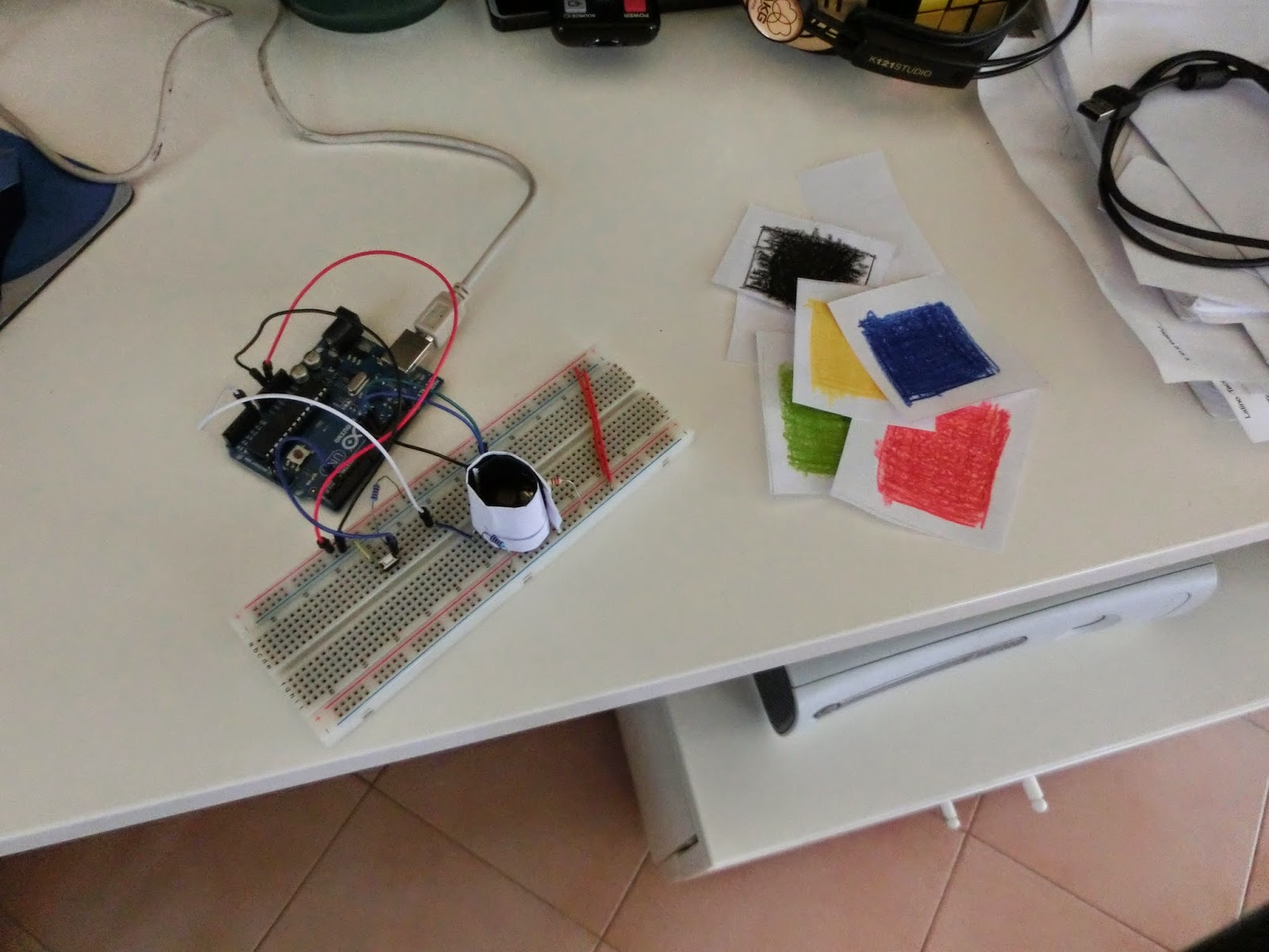
then assemble everything this way:
Here is the arduino code:
/*
Color detector with arduino, RGB led and photoresistor
Code by Damiano Andreghetti (also thanks to the adafruit tutorial about the RGB led)
for more information check my blog: www.ilblogdidami.blogspot.com
Everyone is free to use this code, but I would appreciate if you mention my name
*/
int redPin = 11;
int greenPin = 9;
int bluePin = 10;
int buttonPin = 2;
int buttonState = 0;
int phrPin = 0; //photoresistor pin
//other variables for calibrating and measuring
float calwr, calwg, calwb, calbr, calbg, calbb, r, g, b = 0;
//uncomment this line if using a Common Anode LED
#define COMMON_ANODE
void setup(){
pinMode(redPin, OUTPUT);
pinMode(greenPin, OUTPUT);
pinMode(bluePin, OUTPUT);
pinMode(buttonPin, INPUT);
pinMode(phrPin, INPUT);
Serial.begin(9600);
}
void loop(){
buttonState = digitalRead(buttonPin);
if(buttonState == 0){
Serial.println("button pressed: calibrating white");
calibration();
}
else{
measure();
}
}
float readColor(int times){
float avg, total, current = 0;
for(int n = 0; n <= times; n++){
current = analogRead(phrPin);
total += current;
delay(20);
}
avg = total/times;
return avg;
}
void setColor(int red, int green, int blue){
#ifdef COMMON_ANODE
red = 255 - red;
green = 255 - green;
blue = 255 - blue;
#endif
analogWrite(redPin, red);
analogWrite(greenPin, green);
analogWrite(bluePin, blue);
}
/*
This function is needed because the raw measure is influenced by
environmental light.
*/
void calibration(){
//first calibrate with white color
setColor(255, 0, 0);
delay(100);
calwr = readColor(7);
setColor(0, 255, 0);
delay(100);
calwg = readColor(7);
setColor(0, 0, 255);
delay(100);
calwb = readColor(7);
setColor(0, 0, 0);
//then wait until the button is pressed again
//so we can calibrate with black color
Serial.println("waiting to calibrate black");
for(int i = 0; i <= 10; i+=0){
buttonState = digitalRead(buttonPin);
if(buttonState == 0){
//calibrate with black color
setColor(255, 0, 0);
delay(100);
calbr = readColor(7);
setColor(0, 255, 0);
delay(100);
calbg = readColor(7);
setColor(0, 0, 255);
delay(100);
calbb = readColor(7);
setColor(0, 0, 0);
i = 20;
}
else{
//nothing
}
}
}
void measure(){
float deltacal = 0;
setColor(255, 0, 0);
delay(100);
deltacal = calwr-calbr;
r = (readColor(7) - calbr)/(deltacal)*255;
setColor(0, 255, 0);
delay(100);
deltacal= calwg-calbg;
g = (readColor(7) - calbg)/(deltacal)*255;
setColor(0, 0, 255);
delay(100);
deltacal = calwb-calbb;
b = (readColor(7) - calbb)/(deltacal)*255;
Serial.print(int(r));
Serial.print(",");
Serial.print(int(g));
Serial.print(",");
Serial.println(int(b));
}
Now upload this code to the arduino.
To calibrate the sensor press one time the button (the sketch check the button status before the red light) while a white object is near the sensor, then the led turns off.
Now put a black object near the sensor and push the button another time.
The arduino will start writing via serial the RGB value it detects.
Now we're going to use processing to display the result.
Here is a simple sketch:
/*
Sketch used to display the result of the color detector made with arduino
Code by Damiano Andreghetti based on processing serial
for more information and for the arduino schematic and code
check my blog: www.ilblogdidami.blogspot.com
Everyone is free to use this code, but I would appreciate if you mention my name
*/
import processing.serial.*;
Serial port; // Create object from Serial class
String buff; // Data received from the serial port
int r,g,b = 0;
void setup() {
size(600, 600);
noStroke();
// List all the available serial ports in the output pane.
// You will need to choose the port that the Wiring board is
// connected to from this list. The first port in the list is
// port #0 and the third port in the list is port #2.
println(Serial.list());
// use your port
port = new Serial(this, Serial.list()[1], 9600);
}
void draw() {
if (0 < port.available()) {
buff = port.readString();
String[] list = split(buff, ',');
if(list.length == 3){
r = int(list[0]);
g = int(list[1]);
b = int(list[2]);
background(r,g,b);
}
else{
background(r,g,b);
}
}
else{
background(r,g,b);
}
}
To make everything work connect the arduino, calibrate the sensor, and run the processing sketch.
If there are some problems re-calibrate the sensor and use a dark-color cylinder to isolate LED and resistor from the environment. Like this:
Here are other photos of the project:
Here is also a video of the project:
I hope you like this post, if you have any question comment or send me an email to damianoandre@gmail.com
Bye, Dami


